Hello! I’m back. I’ve been working an awful lot so…………..
New years resolution: Post more.
maybe if i say it enough times it will come true
But yes. So I anticipated just tugging the airplane outside when I wanted to work on it. Simple, right?
One word. COLD.
It’s very windy and cold here and I hate it. So my landlord graciously gave me a garage bay to work in for the winter. I have to be out of it by June. THE RACE BEGINS.
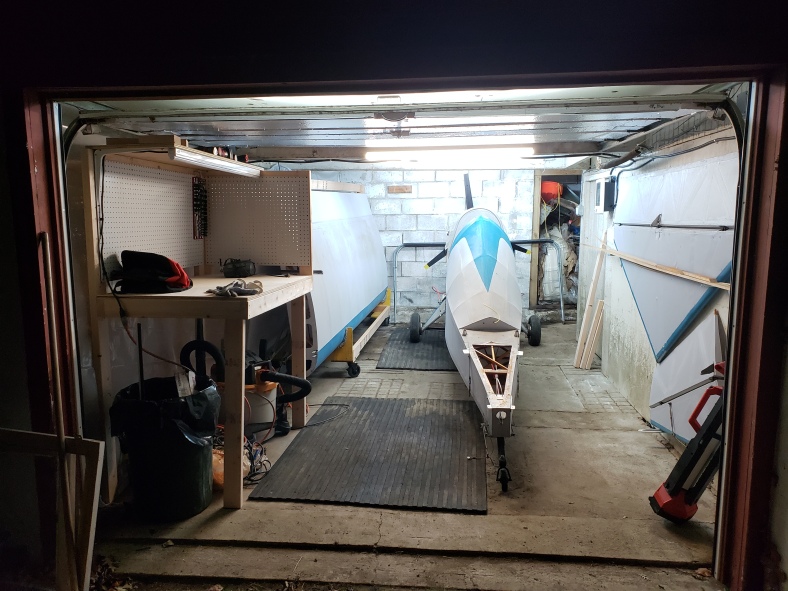
Here is the final product!
Pretty nifty, huh? I added a lot and cleaned a lot!
Keep in mind, this is what it used to look like:
Yeah, pretty big difference.
So the main things I did were to add five 48″ LED bars to the ceiling + 1 on the workbench, wire up two outlet boxes to provide useful tool power around the space, and most importantly, insulate the door, divide my bay from the other bay with thick plastic drop.. cloth.. stuff, and add two 2000W electric heaters! Gloves suck to do work in and I hate cold so here we are. I also got rid of a very, very old dead fridge that was eating up a lot of space. Now I can push the wing cart back a couple feet, allowing a good sized work bench.
There was already switched light power in the garage as well as a high amperage 240V plug, so that was the heaters and lights taken care of. To power the rest of the outlets, a normal 12ga armored cable was ran from the workshop (further to the right of the garage) electrical panel to the garage. … That’s pretty much it. It’s outlets. Woo.
The heaters were nice. My landlord again graciously lended me a smart thermostat that I can control from my phone so when I plan on doing work in there, I can fire it up an hour before and warm the place up! It manages to hit 60F pretty easily and hold it there, and that’s perfect for me. Hoodie temps, but no gloves required. 70F is a bit much, and the heaters never turn off.
Opinion? Love the heaters. The heater in the workshop is a PTC style heater with a large thermal mass in it, which kinda stinks to be honest because it means that the heater ALWAYS needs power because the fans need to cool the element down. If you just cut power to the whole thing when you are done heating, the inner hot core heatsoaks to the outer casing and the thing ROASTS and gets super dangerously hot and the plastic parts on and near it start to get a bit soft. Normally the fan is controlled by a thermal switch that turns it on after the element gets warm and then holds it on for a minute after it shuts down to cool it off safely. But this is annoying to add a smart thermostat to.
The nice part about these cheaper cadet ones is that they have what is essentially a hair dryer element inside, so when you cut power, bam, its all good. Easy to control externally.
I can’t believe I just wrote that much about wall heaters…
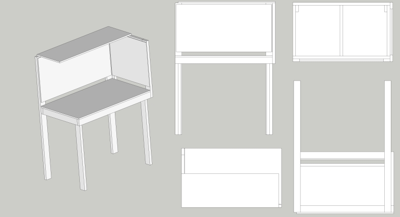
Anyway! So now we have power, heat.. Workbench time! I put way too much stuff down and it just sits on the plane, which is fine until I bump it and then everything topples over. So I designed this quick bench to use some scrap cuts of 3/4″ plywood that I had laying around from when I made my desk in my living room.
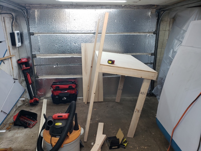
After that, I went to assemble it, aaaaaand…
Oh dear. I hope this isn’t going to reflect my level of craftsmanship for the rest of this project, or the flying coffin warnings I constantly get from everyone might turn out to be correct…
One realizing I lined the marks up with the bottom of the bench-top instead of the top of it and re-doing it later….
We have a nice complete bench! Got a cheap power strip.. thing from Amazon, clipped one of my several extra M12 chargers onto the side, mounted a socket holder because why not.. Cheap amazon chair.. Amazon is going to be a common theme.
Finally, my girlfriend helped me clean out the whole place and vacuum it a bit and then drag in some unclean but now somewhat clean stall mats. Now its quite a nice place!
Doing the foam insulation on the doors was a bit of a hack job but.. it worked. The room went from never being able to crest 50F to easily hitting 60F and the heaters can actually turn on and off at roughly 50% duty cycle. Nice!
That’s honestly it for now. Now that I finally have a nice warm clean place to work, I have no excuse but to finally work on the airplane. First things first, I’ll be tearing it down and pulling lots of parts out of it, to start remaking them to be tall person friendly.
My baby is here. She requires a lot of little things, so.. prepare for that.
I am very excited about this airplane, it’s been a very long dream of mine to fly, and well, here we are. The story of this airplane is one that is very interesting, because as far as I can tell, its as old or older then me, and has never flown! It was made by a retired aircraft mechanic as a hobby project, but before he finished it, he had some heart complications, and decided to stop working on it. It was very close to flying, was stuck in a big shed building, and left to collect dust.
Now, I’m not one to turn down a very good price for an engine, let alone one that comes with a free airplane with 300 hours of labor already completed. That means I fly in 2019, not 2029, given the pace of my projects and blogging.
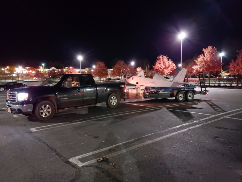
The first part of the adventure was getting the dang thing home. This was not as easy as I anticipated. It turns out that despite a 16ft utility trailer seeming absolutely enormous, when you have a large and very fragile aircraft with parts that don’t like to sit or rub on each other, you use that space pretty fast………
For anyone who finds themselves needing to do this, I found that the winning arrangement (for a minimax anyway) is to angle the plane slightly sideways and put the tail wheel up on a concrete block. Then you stick both wings under the side that has more room (from where its turned sideways slightly) and place said wings curved sides towards each other. There are strut mounts that would dig in and otherwise ruin the wings if it was the other way around. After you do that, liberally apply many moving blankets and hope none blow off (they did) and then even more liberally apply tons of tie down string, hoping that doesn’t loosen up (it did).
Remember kids, use actual tie down string and not just what you had laying around, especially if what you had laying around is pull cord for pulling wire through electrical conduit and is literally designed to be as slippery as possible. Hindsight is 20/20. Thank you very much Nick for helping me do this and bringing your truck and trailer.
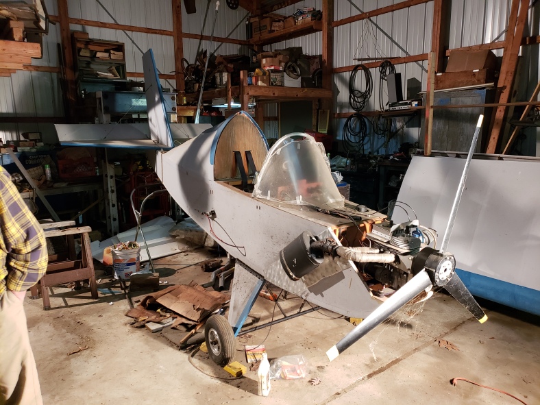
And here we go! An airplane! Sans ailerons because I was lazy. In retrospect they were actually really easy to attach and I should have just put them on. Oh well ¯\_(ツ)_/¯
While horsing around with my friend and landlord, we discovered that the battery, despite not being charged for years, still had enough power to bump over the engine. A dash of 2 stroke premix and some ignition-off spinning to lube everything up, and..
Friend filming, me being cold behind a giant fan on a 43 degree day.
Engine runs nice! Now to tear it all down to inspect everything.. well, not now, but eventually. Once I cart it all upstairs.
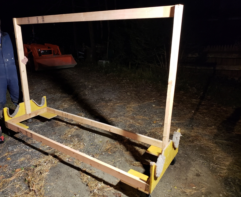
After having our fun, we made a stand to stick the wings on (with ailerons) so it could be safely tucked into the garage.
Now, what to do. Well, a deep clean first, when it STOPS RAINING.
After that, this is my fast and (very) loose checklist. One you’d find sharpied badly onto a piece of torn cardboard and duct taped to the wall.
Preliminary inspection (I have to trust all the glued bits of popsicle sticks before I want to fly my butt around in it.)
DIY Glass cockpit display (because I want it)
Tall person mods (it is not.. able to fit me right now)
Engine work (actual 2 stroke exhaust, better sensors, maybe new mounts?)
Misc repairs to structure (trailing edges of wings have separated slightly)
Misc repairs to fabric skin (some tears here and there)
New paint (because right now, its kind of ass..)
To elaborate on some of these points:
Inspection is going to take a while, and I’ve already found some damage. Mainly in the trailing edge of the wings, in the cavity where the ailerons attach. The issue is that the tension of the dacron wing fabric tugs back on the wood they are adheared to, which due to the small surface area of the glue join between the trailing piece and the wing ribs, causes them to pop off. This is bad.
Based on some forum talking, it appears to be a common issue with the old version of the mini-max (remember when I said this plane is older then me?) I’ve been mulling over a few solutions, and one nice one was offered on the forums, which is to poke some strong thread through the fabric and around the trailing edge wood, and then around the wing rib, knot it all together, soak in glue to stiffen it up, and repeat. I will post details when I get that far.
I am very excited about the DIY glass cockpit display. I’m a sucker for that kind of needlessly complicated stuff, so here we go. I am going for a raspberry PI based system, as well as a ridiculously bright 1000cd/m2 10.1″ IPS display I sourced from Alibaba. I have no idea when it will get here and the sketchy Chinese tracking site seems a bit weird, but hey. It’s by far the brightest HDMI display I could find, and cheap too! 60 bucks each for the display/HDMI driver, and 25 dollars shipping for 2pcs of them. I spied kits of similar LCDs with driver boards at 1/3 the brightness, same resolution, for 140+!
Tall person mods are a must, and will likely be the first thing to happen because what mods have to be made and what ones do not will judge where everything else gets mounted and shuffled.
The main issue is …. I’m not sure what the deal is, but the part where the top deck juts out from the back of the cockpit really causes most of the issues. I’m hoping that widening the hole and moving the seat support rails back, plus shifting the rudder pedals forward will fix my issues.
Where the seat belts hang over is like a 4 inch… spot, and I can’t figure out any reason for it to be there other then to cause misery and pain. It does not have any key structural members in it (as far as I can tell) and only has the seat frame on it. The huge main support beam is behind it, flush with that back seat wall plate thing on the turtle deck.
Engine work is not as much as I thought it would be. The main things are to clean out everything, replace spark plugs, wires, rewire the entire electrical system (because the one right now is sketchy as frig), make a cable or servo to adjust the carburetor mixture in flight, a new drive belt because this one is old, cooling ducts so the engine doesn’t overheat as right now the cooling fins sit directly behind the main propeller pulley and get no air at all, a new exhaust because the current one is not meant for a 2 stroke and so gives no back pressure pulse to supercharge the engine, and possibly new engine mounts.
…….Okay so that is a lot of work. But I shall prevail at the speed of procrastination and bad weather.
Fabric repairs and new paint are pretty self explanatory. Some of the fabric has little tears on it, some old before my interaction, and some entirely my fault being boneheaded transporting it home.
I believe that covers everything. First chance I get, I’ll be working on cutting the old seat frame out and starting to inspect the entire structure for damage, so I can truly find out what a piece of junk my beautiful plane I naively bought without looking at it too hard actually is.
Sooooo. Sorry, zero readers who come here! I will try to be more active now. But we’ll see. =)
I have not picked it up yet.. But soon! This spring, ITman will be flying!
This is a Mini-Max 1030R (I think)! It is powered by a Kawasaki 440 2 Stroke, 2 Cylinder engine, feeding a 3 blade propeller through a reduction drive.
I have purchased it from a retired aircraft mechanic who never got a chance to fly it after mostly building it. So I aim to finish it up over the winter, get some lessons, and then be in the air by spring! I will detail the build as it occurs here, as well as a few other places probably.
So this year didn’t really go very much to plan in terms of, well, /racing/.
To be honest, I was kind of imagining that they were going to make a new award for our team, the award for the car that failed, kept on failing, and died immediately, and generally was a waste of valuable pit space and natural resources. But lets go back a bit in time to see why we failed. Spoiler alert, its procrastination and rushing.
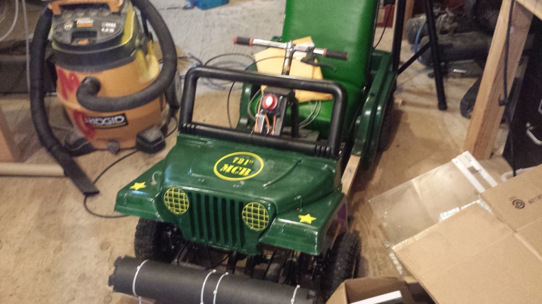
I’m part of the 721st Mechanized Contest Battalion (WC2FD), a HAM radio group / Maker group that dabbles in all sorts of things. In the past, it’s been FIRST, its been youth programs, robots (A claim to fame was the Emergency Antenna Platform System ) and now racing power wheels, among many other things. At some point in the late summer, a member suggested that we participate. I agreed immediately, as I had wanted to do a PRS kart SO BADLY. So we did.
So I threw together a cad design for a kart like my life depended on it. I quite liked it. This design was more or less followed in the final product. The thing I am most proud of is the steering system. I just got a plugin for Sketchup called MS-Physics, which is sort of like SketchyPhysics but.. better? It uses a newer version of whatever physics engine it runs on.
What’s important is I designed a lovely steering system with it. It had proper geometry, as in the inner tire turned as much as it should to follow the corner radius, the outer tire did as well. Also, it had some tilt-back that I read about, to allow it to want to self center, and also jack up the rear wheel on the inside of a turn slightly to lift it off of the ground, to avoid solid axle scrubbing of the faster rotating tire. When the car briefly worked, it handled VERY well. That part was a complete success. It also allowed me to nail the geometry of all the parts, and see that they didn’t hit each other in the design, as well as make jigs to weld them up. No fancy markforged 3D printer here, unfortunately, just a normal one!
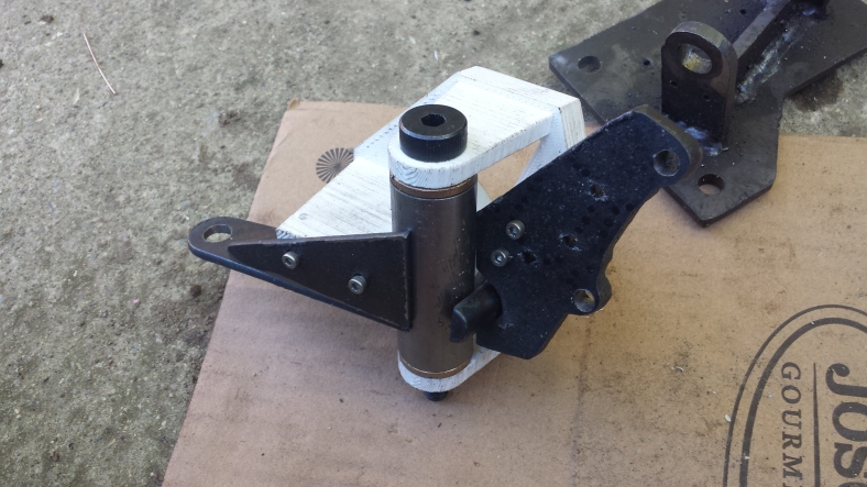
Here you can see one of the 4 jigged plasma cut parts, in its jig, ready to weld. These parts were a bit of a faff to make. I got them plasma cut…. but this is where I learned that plasma cutting is not… neat. It’s certainly not water jetting, that’s for sure. So my idea to make parts, use the plasma to make some small holes for M3 screws to line the parts up on the jigs worked, but not very cleanly. But it did work, and here it is, in it’s jig. This part, I feel, would be extremely difficult to weld by hand and get all the angles correct. It has very strange twists and tilts to make all the geometry work properly.
Here it is, all welded. With some grinding. May I also remind you that I only have a few days of MIG welding experience? I think I’m doing pretty good. However, for anyone considering doing this, may I just make a note? One, a beefy 3/8″ spindle bearing ID size seems good, but it isn’t. Use bigger bearings. Also, it’s extremely important to take the plastic jigs off quickly after you spot weld, and…… most certainly whatever you do, do not decide to fully weld the part with the plastic on. It doesn’t end well. It may catch on fire.
Just a hunch.
With the front half going well, lets tackle the more disastrous rear half, containing the drive train. I think the most lessons were learned for me here. Here are but a few:
1: Set screws suck. Use key ways.
2: The VESC is a powerful device, but only if you know how to set it up. I didn’t. It failed pretty terribly.
3: Check your spare VESC’s to make sure they have firmware loaded onto them before bringing them along as spares. Even if they claim to come ready to plug and play, make sure you test your spare parts.
4: Long wire runs. BAD. Bad for the capacitors and bad for life.
5: Proper motor/voltage/gearing choice is very important and can make the difference between doing well and failing immediately and wasting everyone’s time.
First in the list of disasters was the fact that we knew none of this was going to happen, because the kart was finished at 3:30 am the night before, and the electronics weren’t even installed yet. I just want to mention here how hard everyone involved worked to get this thing going. I was there pretty much all week and throughout that week everyone else was pulling long hours to get this thing going. It’s amazing we even made it to the race in the first place, given how the car looked even the day before, with no steering, no drive, no controls, no handlebars, no hubs… This was definitely a team effort and a success in that regard, I just let the design down a bit. The first time it even moved, was during its sighting lap. This is a Bad Idea for what should be obvious reasons, but I didn’t have a choice. The race was when the race was, and the kart was as built as it was at the time. Oh well.
But again, I’m getting ahead of myself. Lets look at the drive train. This is a 2 stage belt reduction drive off of a positively enormous (but I guess not that big) out runner motor. It drives a 15 tooth HTD-5mm pulley, which goes to a 60 tooth, and then that couples across an intermediate shaft to a 20 tooth, which goes into a 60 tooth. This results in a 12:1 ratio, which was supposed to mean a theoretical top speed of around 20mph. We got maybe 7, or 8mph, due to Big Unhappy Problems with the electrical system. There is a 3D printed duct around the motor and a screaming 15,000rpm 40mm server fan forcing air into it and through the windings. Was this effective? I have no idea, the kart didn’t run for long enough to make any meaningful heat in the motor, battery, controller, or anything.
Here you can see the first stage belt drive from the motor to the intermediate shaft. The idler pulley was not actually part of the design, but I actually managed to measure the belt wrong and it was much longer then intended. So… sneak an idler pulley in there and call it a day? The other pulley did not turn out to need this.
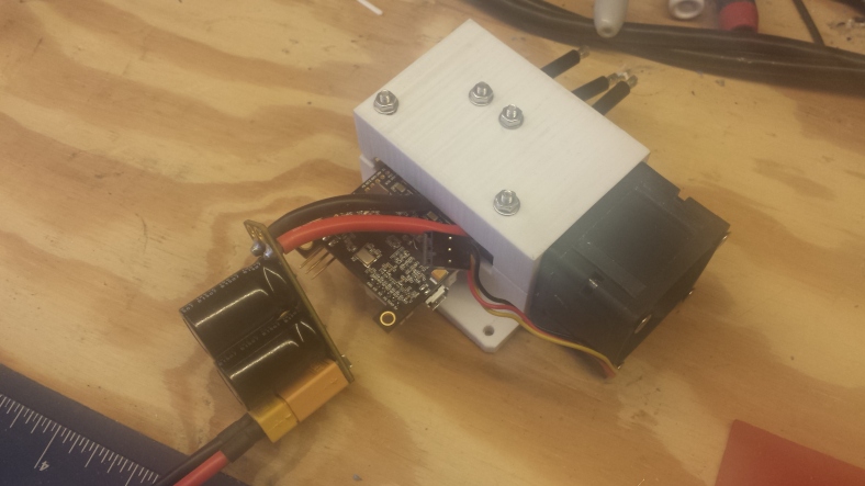
Here we have the VESC. I have encased it in twin heat sinks thermal pasted onto the FETs, and another screaming 40mm fan to force air through the whole mess. This was just to try and keep things a little cooler. But it should not have needed it, this was just me being paranoid.
The VESC is a big topic upon itself. I won’t explain too much, as most people have probably heard of it already. Put simply, it’s an open source speed controller, probably one of the most advanced in the world. It supports a heck of a lot of things, but it needs to be set up properly and also, properly matched with the other components in the system, not unlike any other controller. I’m used to drones, not ground vehicles, and this showed, because I did not do a very good job at this.
The main reason I wanted to use this special controller was because it appeared to be ideal. It is designed for ground applications, and rather uniquely to it, it has a current control scheme. Meaning, you can tell it how many amps you want it to draw, and it will spin the motor hard enough to draw that, and no more. This seemed like a very logical choice when you consider that PRS rules mandate a fuse in the cars to limit power. With this, I would not have to worry about blowing fuses, or having to under size my power system to handle me being a 200lb gorilla at the controls. I could simply set the maximum draw to be the maximum the fuse could cope with, and be on my merry way. I could also exploit the slow-blow nature of the fuse to command momentary bursts of larger, but still precisely controlled, power draws.
I could also use this to allow myself to have even more power, in theory, by over sizing my electric motor dramatically, and under driving it at the lower speeds at 60A when it would realistically draw more, and then as the speed increases and smaller motors start to top out, the motor would just be coming into it’s stride. This may not work as well as it sounds in theory, as it turns out, and I’m not sure if it matters. Motor top speed is never what the top speed under load is, which I conveniently forgot. Someone smarter then me will have to tell me if this idea is sound.
These are the circuit boards I originally intended to use in the kart. I custom made them in a hurry, and they are now a complete waste of money. Maybe the dashboard board is usable in the next iteration, but the main board certainly isn’t, which is a shame. I plan on using a Raspberry Pi to control an LCD in the next version, so the dash one may not see any use either.
The main board was intended to talk to everything in the car. It would measure the balance of all the LiPo cells, it would measure the temperature, it would read the potentiometers for the brake, gas, and a button for ‘boost’, and send all the information to the VESC via UART, commanding a certain number of amps to be drawn. It would also gleam information back from the VESC, such as amp draw, voltage, rpm, status of the system, temperature of the controller, etc, and send it over a cable to the dashboard, which would display it by moving servo driven needles much like a car, as well as some neopixel RGB leds behind masked symbols, again, like a car, to act as idiot lights. Unfortunately, none of this got finished in time, and now its a waste. The new system is running at much higher voltage levels that this can not cope with, and I am no longer using potentiometers, or potentially even needles. So that was a waste of a hundred bucks. =(
So here we are, race day, in the pits, next to FUBAR labs, and I’m in the picture wiring an Arduino pro mini to act as a servo tester to control the damn thing. What a mess. I had such visions of grandeur for the electronics, and here I am, hard soldering in a tiny Arduino and taping it up so it doesn’t short against the frame. Sigh.
We got the kart going, somehow, and limp around the track for it’s first lap. It kept cutting out when I gave it more then half throttle, so I came back in and raised the current limit. Side note, if you have to remove the body of your car and unbolt the seat and it takes five people ten minutes to get to the electronics of your vehicle to plug in a damn usb cable, you’re doing it wrong. Quick access is key, especially on something untested.
I raised the limits, thinking that was the problem, and carried on. I went to go out again, and right as I was about to pull out onto the track, I hit the throttle, and heard the motor spinning, but nothing was happening, and I wasn’t rocketing out into fame on the circuit. I was sitting there, in people’s way, trapping everyone behind me in the pits.
What had happened is set screws had happened. The torque from the motor had spun the set screws into a ring around the shaft, mangling them so they would not come out easily, and making it so the pulley spun freely around the D shaft, but would not come off. Very wonderful people from a team I could not remember from MIT helped us pull the car into their pit, as we could not get to ours through the line of trapped karts, and helped us pull the assembly apart, drill some spot drills for the set screws to have more grip in, and got us on our way. We owe you one, whoever you guys were.
With that issue sorted, we made it onto the track! It was race time! It still did the throttle cut thing, but it was okay, as long as I was careful, it seemed to work just fine. Four laps went by, and I even passed a few people! Slow people, but still! And then it died. It came back to life briefly, and then died again, and stayed dead. I had blown the fet driver of the VESC, as told by the 3 blinking red lights of death on it. We pulled the car into the pits and went to replace it, but the spare had no firmware. Sigh. Game over. Five total laps, weeks of work, traveling all the way to Maker Faire NYC. Five. Laps. Slow laps, too, not even blazing glory laps.
So after doing our sixth and seventh victory laps via good old human push power, what have I learned from this?
Electronics are hard. Even if you think you are smart, you aren’t, not really. Stuff does not translate domains very well. You might be intimately familiar with a system, having used it for years in similar applications. But stuff does not scale very well. RC cars and drones are not go karts. More importantly, set more time aside for things. Test stuff before bringing it. Your maiden smoke test should not be the race you’ve entered.
What are the improvements for next year? I’m going to step the voltage up to 12S 44.4v, use a different motor, one with a lower Kv, more torque, and sensors in it for better startup. I’m going to add a metric butt-load of capacitors, and keep my wiring runs much, much shorter. I’m going to have instrumentation, to see failures before they take out equipment. I’m going to talk to experts who have used these devices to do these things, and get their advice on component choices.
And most importantly, I’m going to have a whole year to work on this and have at least a hundred hours of abusive testing on the kart before it ever sets a wheel near a power racing series circuit again.
Maybe this time I’ll actually impress the people I look up to instead of getting in the way on the track with a dead kart.